Power MOSFETs enable a huge range of electronic systems, specifically in situations where BJTs are not useful or efficient. MOSFETs can be used in high current systems in parallel arrangements, but what about their use in series? You don’t often see either arrangement in smaller switching converters simply because there are many off-the-shelf MOSFETs that can provide the required current without failing. However, once you start looking at delivering high voltage/high current using a switching system with a small footprint, you’ll need to consider these arrangements of MOSFETs.
Both arrangements of MOSFETs have their pitfalls that designers should consider. Let’s look at MOSFETs in series as they are quite useful in certain systems, but be careful to design your circuits and your PCB for reliability.
Using Power MOSFETs in Series
An array of MOSFETs in series will have their sources and drains connected to each other. This arrangement can then be used to drive a low-Z load in series, or a high-Z load in parallel. The simplest arrangement of MOSFETs in series is shown in the following circuit diagram:
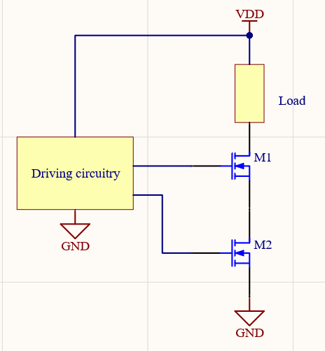
In this circuit, VDD is distributed over both of the MOSFETs according to Kirchhoff’s voltage law. Both must be switched ON at the same instant in order for current to flow through the load. This is basically operating like an AND gate, but potentially operating at very high voltage or current.
The other possible arrangement is to use series MOSFETs in a push-pull arrangement, just like CMOS buffers:
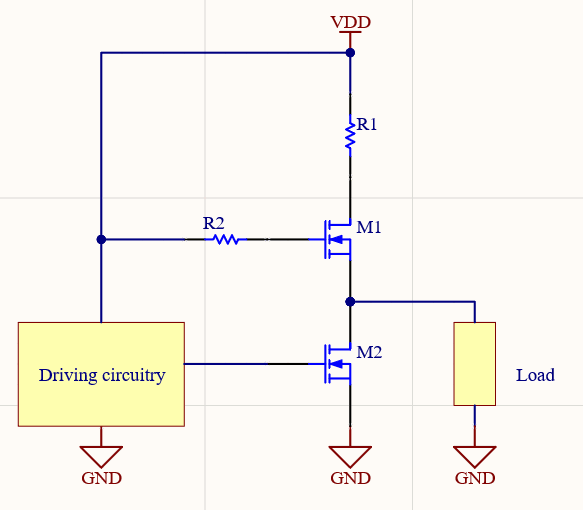
In this type of circuit, the lower MOSFET (M2) can divert current from the load by being switched ON or OFF as long as the top MOSFET (M1) is ON. This would be ideal for a high-Z load, where M2 acts simply to divert current when it is not needed at the load.
There are many other examples of MOSFETs in series you can formulate. Some applications for these arrays of MOSFETs in series include:
Current-fed power inverters
High-voltage stroboscopes
High-voltage resonant tank drivers
Push-pull driver circuits for Vg MOSFETs
High-voltage specialty logic buffers and amplifiers
Multi-phased switched drivers
You’ll notice that these applications contain the term “high voltage” for a good reason, and it relates back to the fundamental reason we use elements in series to begin with. To see why, it helps to compare these circuits with MOSFETs in parallel.
MOSFETs in Series vs. Parallel
In an earlier article, I brought up some points about placing and using MOSFETs in parallel, as well as some of the electrical behavior that might result in these circuits. The main reason MOSFETs are placed in parallel is to get access to larger current when all the MOSFETs switch ON simultaneously. Because these transistors are placed in parallel, their output currents add together according to Kirchhoff’s current law. This is not exactly true as you need to add some small resistances to suppress any parasitic oscillations, especially in a high power system. However, the analogy to parallel circuits works well and effectively describes what happens when the entire array is switched ON at the same moment.
In effect, the array acts like a single transistor with a much larger current rating but the same voltage rating. This arrangement is a standard way to drive high-current motors, supply current in a high-current switching regulator, or any other system that requires a lot of current from a switching element. The same idea of summed voltage ratings does not actually apply to series MOSFETs for a few important reasons.
Series MOSFETs Can’t Always Handle More Voltage
In the series arrangement, the idea is that the group of MOSFETs will act like a single large MOSFET with a much higher voltage rating but same current rating. This does not always work out in practice.
To see why, consider a case where VDD = 100 V in one of the circuits above . We could conceivably use identical MOSFETs with maximum voltage ratings of 50 V; by placing them in series, they would each experience only 50 V, rather than the full 100 V. Now consider what happens if M2 is switched ON while M1 is OFF: M1 has high R_off resistance, so it takes the entire 100 V and exceeds its 50 V rating, and subsequently it fails.
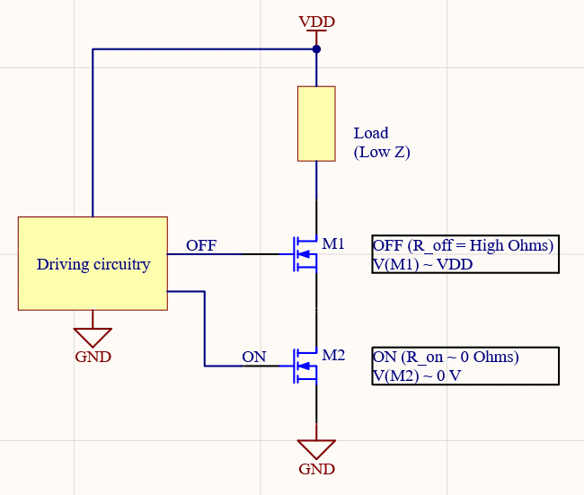
This should illustrate the importance of the driving circuit in the first diagram above: everything needs to be switched on at exactly the right moment. If you’re using MOSFETs in series to drive an inductive load or resonant tank load, it’s strongly recommended to also place capacitors and some ESD protection (e.g., flyback diode) to prevent a large voltage spike from destroying your MOSFETs.
Parallel, Series, or Both?
There is no hard rule about when to use either parallel or series arrangements of MOSFETs. Parallel arrangements are standard in systems that have high power delivery requirements and that require fast switching, such as with a PWM. Motor driver circuits are perfect examples. Meanwhile, series arrays would be needed for high voltage delivery, and not necessarily high current. If you think about it, you could certainly use a combination (multiple series arrays, all placed in parallel), although your driving circuit becomes very complex as a result.
An example circuit diagram showing a combination of series and parallel MOSFETs is shown below. I’ve left a block in this diagram for the load and driving circuits, the latter of which can be very complex. Such a driving system would require some logic and possibly a fast feedback loop to operate properly and ensure each series leg is fully turned ON when driving the array.
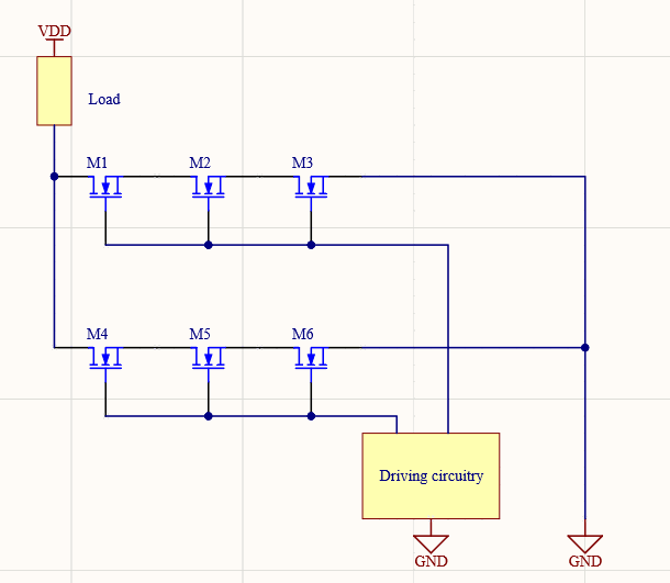
Another option that is enabled with MOSFETs in series and parallel is multi-phased switching. When the parallel MOSFETs are each driven with the same PWM frequency, but they are separated in phase, the array behaves as it is being driven with higher frequency. This is one trick to get to very low noise operation in a switching converter. While you can’t do this with a standalone array of MOSFETs in series, you could combine series legs in parallel to create phased drivers as shown above.
This is a very effective trick for reducing noise in power systems while still operating at high frequency, such as in an RF power supply where higher frequency operation is desirable. I’m planning to cover a multi-phased power converter in an upcoming article as these converters are critical for powering low-noise, high-frequency analog systems, such as RF power amplifiers. This is one area of power conversion that is seldom discussed and it requires more complex driving circuitry, but it’s an effective technique and standard topology in many systems.
When you need to design, simulate, and layout your power systems with MOSFETs in series or parallel, use the complete set of PCB design, layout, and SPICE simulation features in Altium Designer®. When you need to examine EMI from power systems, you can use the EDB Exporter extension to import a design into Ansys field solvers and perform a range of SI/PI simulations. When you’ve finished your design, and you want to release files to your manufacturer, the Altium 365™ platform makes it easy to collaborate and share your projects.
We have only scratched the surface of what’s possible with Altium Designer on Altium 365. Start your free trial of Altium Designer + Altium 365 today.