Electromagnetic interference (EMI) is such a problem that governments around the world have placed limits on the amount of EMI an electronic device is allowed to generate or receive. Your electronic device needs to be designed to prevent unintentional radiation and suppress conducted noise up to a very high frequency value. This is not a simple matter of adding filtering on every circuit in your PCB layout, it’s about considering the entire system and its construction.
Modern techniques in EMI shielding fall into two areas: board-level electromagnetic shielding and enclosure-level electromagnetic shielding. There are some board layout practices that can help ensure a design passes EMC tests, and there are some simple changes to an enclosure that can help prevent excessive EMI from being detected in the system. With the right PCB design software, designers can implement both sets of solutions and ensure their manufacturer has sufficient documentation to build the design correctly.
Today’s modern devices must undergo electromagnetic compatibility (EMC) testing if they are ever to make it to market. The idea behind these tests is simple: measure electromagnetic radiation emitted from an electronic device and the resulting electromagnetic interference. In the event a board does not pass these tests, it needs to go back to the designer for rework, creating greater expense and more time to finish a new project. However, some basic design strategies can be implemented in your PCB design software to help you pass these tests successfully.
EMI shielding can also be implemented in an enclosure in the event board-level solutions fail. If you’ve ever needed to rework a board and enclosure to implement these solutions, then you know how important it is to be efficient and quickly implement changes to a board. Altium Designer’s complete set of PCB layout features and MCAD collaboration suite are ideal tools you can use to implement both sets of EMI shielding techniques.
Implementing EMI Shielding in Your PCB Layout
There are some simple yet effective ways to apply EMI shielding in a PCB layout. There are some component and materials companies that supply specialty electromagnetic shielding materials targeting a range of frequencies. When initial methods like filters and best layout practices fail, you can use the following features in your PCB layout:
Metal shielding cans can be custom fabricated and mounted around noisy circuits to suppress excessive electromagnetic radiation.
Elastomer electromagnetic shielding materials can be used to target specific components and connectors in the PCB layout to suppress electromagnetic radiation.
High electrical conductivity mesh materials can be used as a flexible alternative to rigid shielding cans, particularly in flex or rigid-flex boards.
Replacing separated/star ground with uniform ground planes provides multiple grounding points and helps ensure conductive shielding materials can be grounded easily.
Ferrite beads, rods, and plates can be used as targeted EMI filters when conventional filter circuits fail.
These are some simple methods and components that can be accessed from various vendors and incorporated in your PCB design software. However, you should still make sure to implement some best practices in your PCB layout to ensure the design can pass EMC tests.
The Best PCB Layout Tools Help You Add EMI Shielding
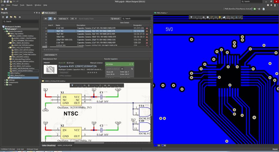
Depending on how your PCB layout is arranged, it can also provide EMI shielding thanks to the arrangement of copper features in the design. How the design is routed and how the PCB stackup is constructed will influence whether your electronic devices can pass EMC testing. With the best PCB layout utilities, such as those in Altium Designer, you can easily implement best routing and layout practices to help you prevent EMI and apply additional EMI shielding materials in the design.
Ground all un-referenced copper features in the PCB layout and fill in empty spaces with ground plane. Make sure you use the appropriate spacing between controlled impedance traces and any ground pour.
Your ground plane will act as a form of shielding and will provide some protection against EMI from inside and outside your PCB layout.
Some conformal spray coating materials can be used to suppress electromagnetic radiation generated by noise on the power bus noise.
Enclosure-Level EMI Shielding Techniques
When board-level EMI shielding measures are ineffective, either because they cannot address a high frequency range or because EMI is too intense, such as you might see in high current switching regulators. In this case, enclosure level EMI shielding techniques can be used. These include:
Applying metal cans or mesh materials to mating surfaces to close gaps in an enclosure
Applying flexible elastomer materials to mating surfaces in harnesses and pipe fittings
Applying grounded mesh or metal sheets in a plastic enclosure to create a lightweight electromagnetic shielding cage
Using a high conductivity gasket EMI shielding material on circular mating surfaces
These solutions are simple, yet they are effective for preventing electromagnetic radiation from escaping an enclosure if EMI is a problem. These solutions tend to be broadband up to high frequency, and they tend to be cost-effective in that they generally don’t require modifying the PCB layout or require minor changes to an enclosure. All of these shielding, enclosure, and board-level requirements need to be communicated to the fabrication and assembly teams with standard documentation to ensure successful manufacturing.
A Complete Set of PCB Layout Features for Power Supply Designs
During volume production, your manufacturer and assembler needs to know how you intend to use these materials and where they need to be applied. In order to ensure designers can implement these solutions without creating mechanical interferences, the mechanical design team needs to have access to the PCB in MCAD software to complete a backcheck with the EMI shielding materials added to the enclosure. In addition, assembly needs to be aware of these requirements and they should be clearly communicated in standard drawings.
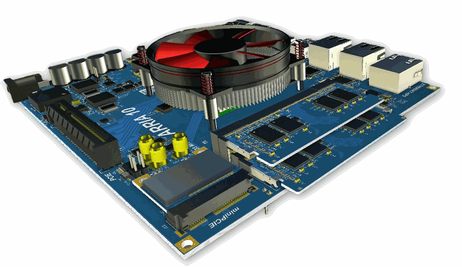
Altium Designer does more than give you the best PCB layout tools. Designers can import their boards into popular MCAD applications and design an enclosure around the board that includes shielding measures to suppress electromagnetic radiation and interference. Once enclosure requirements are defined, it’s easy to write these into standard assembly documents and drawings using the Draftsman utility in Altium Designer. You’ll have an entire toolset for product development and manufacturing.
Implementing enclosure-level EMI shielding techniques requires design software that integrates important ECAD and MCAD features into a single program.
In addition to MCAD applications, Altium Designer users can import their board into Ansys field solver applications to evaluate EMI reduction strategies and pinpoint EMI hotspots in a PCB layout.
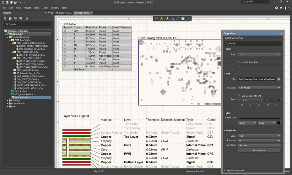
When you’re ready to have your new power supply design produced, you can get started creating your documentation with a set of integrated manufacturing features in Altium Designer.
A Complete Toolset for Implementing EMI Shielding
Altium Designer is the industry’s premier PCB layout program that integrates with many other design applications. Thanks to integration with SolidWorks, PCT Creo, Autodesk Inventor, and Fusion 360, PCB designers and mechanical teams can work together to implement EMI shielding techniques at the board level and enclosure level. Everything needed to quickly generate the required outputs from design data is included in Altium Designer, offering product development teams a complete solution for PCB design and manufacturing.
Stay Productive in Altium’s Rules-Driven PCB Design Software
Altium Designer’s circuit design, layout, and documentation features were built to work together thanks to its rules-driven design engine. No other design platform provides the same level of productivity or is as easy to use as Altium Designer. When you use Altium Designer, your design tools will help you catch design errors as you create your PCB layout, helping you stay productive in advanced electronics design.
When you need to use the best design features for design documentation for your printed circuit board, look to Altium Designer, the industry leader in PCB design and manufacturing.
When you’re ready to push your design data into manufacturing, you can use the Altium 365 platform. Every Altium Designer can use Altium 365 to collaborate with their manufacturer via a managed cloud platform.
MCAD users can access Altium Designer PCB layouts and 3D models via the Altium 365 platform with the MCAD CoDesigner extension.
EMI reduction with electromagnetic shielding is a complex topic, but reducing electromagnetic radiation and interference in a PCB layout is critical for products that are taken to market. When you use the best PCB layout software that integrates with other industry-standard design applications, you can implement the EMI shielding techniques discussed here and take full control of your design. Make Altium Designer the cornerstone of your EMI suppression strategy with its complete set of PCB design tools.
Altium Designer on Altium 365 delivers an unprecedented amount of integration to the electronics industry until now relegated to the world of software development, allowing designers to work from home and reach unprecedented levels of efficiency.