Join Altium Designer training this August to get 20% off.

(in-class Training Course)

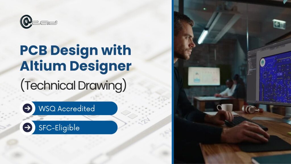
PCB Design with Altium Designer (Technical Drawing)

Course Overview

PCB Design with Altium Designer (Technical Drawing) course provides learners with an in-depth understanding of various aspects of Altium Designer. Participants will explore the User Interface, create schematic drawings with error rule checking, and develop PCB layouts incorporating design rules, routing techniques, copper pours, and design rule verification. The course also guides learners through generating essential output documentation, including fabrication outputs, assembly outputs, bills of materials (BOM), and PDF files. Additionally, participants will gain expertise in library creation, multi-sheet design, and best practices for managing complex projects efficiently.

Who should attend?

This course is ideal for electronics engineers, PCB designers, and technicians seeking to enhance their skills in PCB design using Altium Designer. It is also suitable for engineering students, hobbyists, and professionals transitioning into PCB design or looking to improve their proficiency in managing complex design projects efficiently.

Prerequisite

Learners should have a working knowledge of the Windows operating system. A basic understanding of electronic components is essential to facilitate learning in schematic and PCB circuit design. 

Minimum pax per class: 2

Maximum pax per class: 6

System Used

Altium Designer 24 (Window OS)

Course Outlines

Module 1: Altium Designer Environment

Module 2: Start with Project

Module 3: Design Documents and Schematic Template

Module 4: Schematic Libraries and Components

Module 5: Schematic Drawing

Module 6: Alignment to Organization Strategies

Module 7: Common Challenges and Best Practices

Module 8: Design Rules

Module 9: Routing

Module 10: Polygons Pour

Module 11: Documentation Outputs

Module 12: Outjob Files

Module 13: Schematic Symbol Creation

Module 14: PCB Component Creation

Module 15: Component Creation

Module 16: Integrated Libraries

Module 17: Altium 365

Expected Outcome:

By the end of the course, learners will be able to:

  1. Create metrics and guidelines as part of the production of technical drawings.
  2. Develop solutions using different methods and types of technical drawings to solve problems during the development phase.
  3. Evaluate various types of technical drawings to determine their construction needs and their contribution to design solutions.
  4. Assess the technical drawings for accuracy and according to the specification and standards.
  5. Examine technical drawings and changes using design documentation to ensure alignment with organisational strategies.
  6. Verify drawings and specifications for conformance to relevant standards using Altium Designer.
PCB Design with Altium Designer (Technical Drawing)
Price

SG$ 1,600.00 (Before GST)

No payment required yet.
Contact Us

For any special inquiries, feel free to contact our team by clicking the button below:

Register for PCB Design with Altium Designer (Technical Drawing)

No payment required yet.